


| NO | Title | Description |
| 1 |
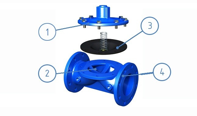
Easy of Maintenance and Clean
|
Just dismantle the upper cover to maintain and clean it. No need to dismantle the whole valve from the pipeline.
|
| 2 |
Simple Structure
|
Easy to dismantle, only one diaphragm as the consumption material, not easy to be blocked by foreign materials.
|
| 3 |
Anti-Shock Diaphragm
|
It can make the valve operation smooth, eliminate the shock, and avoid the damage caused by water hammer problems.
|
| 4 |
Antirust Painting
|
It makes the valve body a better antirust function, and extends the valve life.
|
Comparison of Valve
| Item | Model 47 diaphragm control valve | Other valves |
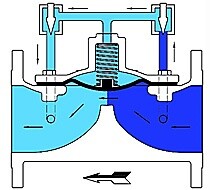
| Structure Drawing |
 |
 |
| Structure |
Simple structure, less components, riskless assembly, less valve operation, less consumption materials and lower fault rate.
|
Complicated structure, more components, easy to be blocked by foreign substances, valve operation by the piston moving back and forth. O-ring is easily damaged by friction.
|
| Maintenance |
It is easy to check and replace the pipelines as they are at the outside of the valve. Just dismantle the air chamber set for maintenance, no need to dismantle the whole valve.
|
No way to check and replace on the pipelines as part of them are inside the valve. Need to dismantle the whole valve for maintenance, which is very inconvenient.
|
| Control |
The area ratio between the diaphragm and pipeline is over two times. So, sensitivity and stabilization are good and control is accurate. The filter is built inside to avoid the blockage by foreign substances. The spring diaphragm can slow down the valve operation to get stable control, endure the shock and avoid the damage caused by water hammer problems.
|
The area ratio between the piston and pipeline is small. So, sensitivity and stabilization are worse. It possibly doesn’t work normally during low pressure. There is no filter built inside. The inlet hole of air chamber is easily blocked by foreign substances. The piston won’t endure the shock, the control is not stable and it is easy to occur vibration and noise.
|
| Fittings |
There is a Flow-Rate Control Valve to control the rate of flow and adjust the open/close speed of the valve, and reduce the water hammer problem.
|
The speed of open and close cannot be adjusted. If the water hammer problem happens, there is no way to overcome and eliminate the problems of vibration and noise, even worse, the valve pipelines would be damaged.
|
| Others |
When the valve is fully opened, there is no any fittings to block from inlet to outlet. It is insensitive to foreign materials and substances, so, it is not easy to be blocked.
|
From inlet to outlet, there are valve set, valve enhanced tendon, etc. among the pipelines. They are sensitive to foreign materials and substances, especially to the banding substances, which are easy to get into the cylinder to damage the cylinder, piston and sealing, etc. and the air inside the air chamber cannot be exhausted. That will affect the stability of valve and cause the breakdown.
|
 |
 |
 |
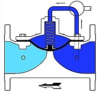
| ● Close ● |
● Open ●
|
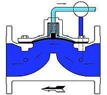
● Control ●
|
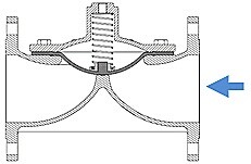
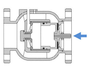
| When the pressure gets into the air chamber from the inlet of the valve, the valve will form an airtight seal. |
Once the fluid in the air chamber is discharged, there is no way to save the pressure in the air chamber. The valve will be opened and let the fluid pass through.
|
If the corresponding control appliance is assembled, the valve will automatically operate according to the pressure in the pipeline to guarantee the input/output pressure and rate of flow.
|
Connection Way
Working Temperature and Media
Operating Pressure
| Flange Class | Max. Working Pressure | |
| bar | psi | |
| 10K | 14 | 205 |
| 16K | 22 | 320 |
| 150LB | 17.4 | 250 |
| PN16 | 16 | 235 |
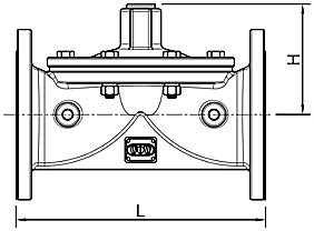
Dimension
|
Valve size
|
50 |
65
|
80
|
100
|
125
|
|
L (mm)
|
200
|
220 |
285
|
307
|
370
|
|
H (mm)
|
87 | 109 | 115 | 137 | 142 |
|
Weight (kg)
|
7
|
9 |
16
|
18
|
37
|
|
Valve size
|
150 |
200
|
250
|
300
|
|
|
L (mm)
|
390
|
500 |
605
|
650
|
|
|
H (mm)
|
164 | 183 | 244 | 258 | |
|
Weight (kg)
|
48
|
83 |
120
|
140
|
Kv/Cv Value
|
Size
|
DN50 (2″)
|
DN60 (2.5″) |
DN80 (3″)
|
DN100 (4″)
|
DN125 (5″)
|
DN150 (6″)
|
|
Cv
|
100 |
158
|
185 |
215
|
400
|
610
|
|
Kv
|
87 | 136 | 160 | 185 | 345 | 525 |
|
Size
|
DN200 (8″)
|
DN250 (10″) |
DN300 (12″)
|
|||
|
Cv
|
925 | 1490 | 2115 | |||
|
Kv
|
795 | 1280 | 1820 | |||
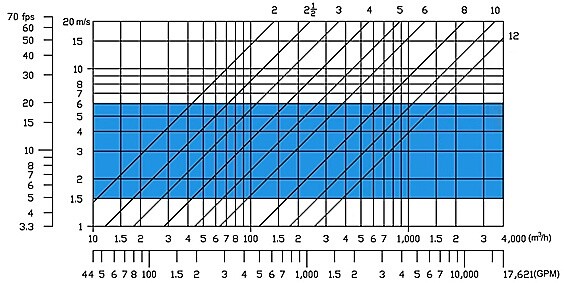
Valve Sizing Method
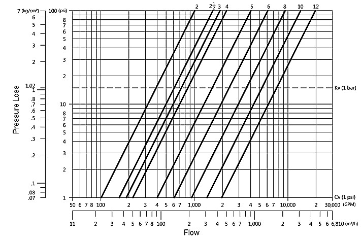
Pressure Loss Curve
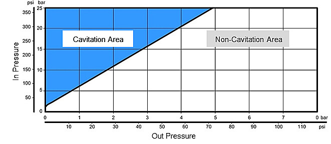
Cavitation Area
Download