


41-05 Hydraulic Balancing Valve-SUS
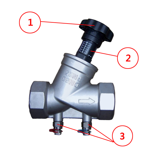
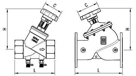
Thread (2″ and below)
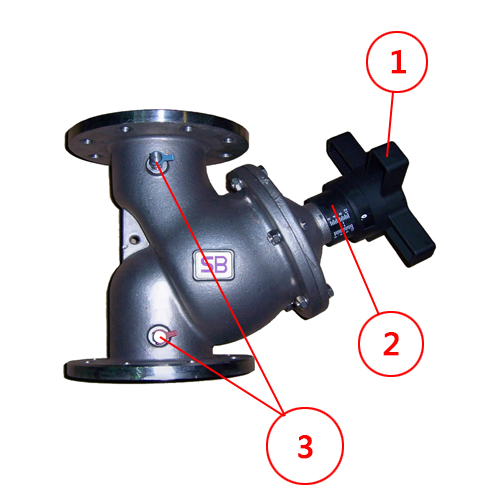
Flange (2.5″and above)
|
1 |
Turning Wheel |
|
2 |
Turning Indicator |
|
3 |
Measuring Connector |
Distribution of flow
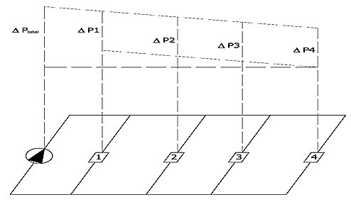
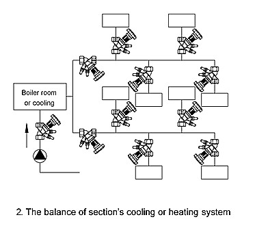
If the drag in some parts of the piping is unbalanced, it will lead to unbalanced distribution of flow. The disposal to this problem is to install a Balance Valve in the piping and use a specific adjusted instrument to balance the drag in the system.
The illustration shows that the pump has to produce a differential pressure at least ΔPtotal to guarantee a sufficient supply to appliance 4. This will, however, inevitably result in an excessive differential pressure at the appliances 1 to 3. Such high a differential pressure will cause overheat or under heat and a waste of energy.
|
Q |
:Flow rate of fluid through the balance valve(m3/h) |
|
Kv |
:The balance valve’s resistance modulus, which can be adjusted |
|
ΔP |
:Different pressure before and behind the balance valve(bar) |
Kv is a modulus of a balance valve. It means, if the differential pressure before and behind a balance valve is 1 bar(1.02 kg/cm2), the flow rate through the balance valve is Kv(m3/h). And the valve’s Kv will no changes if the open rate of the valve’s core is not changed. That is, the opening rate of a balance valve determines the valve’s Kv.
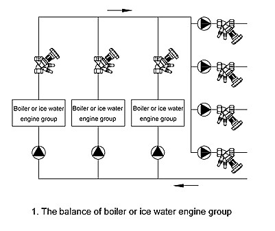
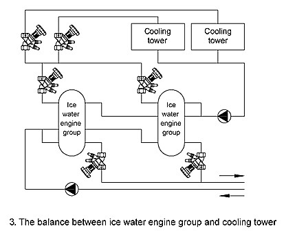
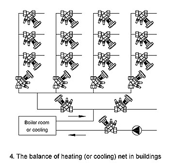
The balance valve can be used in following conditions
Dimension
|
Size |
Material |
Connection |
L(mm) |
H(mm) |
C(mm) |
|
DN20 |
Stainless Steel
|
3/4″ Thread |
84 |
130 |
70 |
|
DN25 |
1″ Thread | 96 | 130 | 70 | |
|
DN32 |
1-1/4″ Thread |
110 |
145 |
70 |
|
|
DN40 |
1-1/2″ Thread | 120 | 150 | 70 | |
|
DN50 |
2″ Thread |
150 |
160 |
70 |
|
| DN65 | 2-1/2″ Flange | 229 | 285 | 210 | |
|
DN80 |
3″ Flange |
250 |
300 |
210 |
|
|
DN100 |
4″ Flange | 327 | 330 | 210 | |
|
DN125 |
5″ Flange |
370 |
355 |
210 |
|
|
DN150 |
6″ Flange | 424 | 370 | 210 | |
|
DN200 |
8″ Flange |
500 |
500 |
300 |
|
|
DN250 |
10″ Flange | 605 | 540 | 300 | |
|
DN300 |
12″ Flange |
725 |
560 |
300 |
|
|
DN350 |
14″ Flange | 733 | 655 | 300 | |
|
DN400 |
16″ Flange |
990 |
825 |
540 |
|
|
DN450 |
18″ Flange | 1000 | 845 | 540 | |
|
DN500 |
20″ Flange |
1100 |
920 |
540 |
Note:
※King-Tech reserves the right to make any revisions on the valve model and size without prior notification.
※When making any design drawing, installation drawing or construction drawing, please do get our approved CAD with our signature, or we will not be responsible for any mistake.
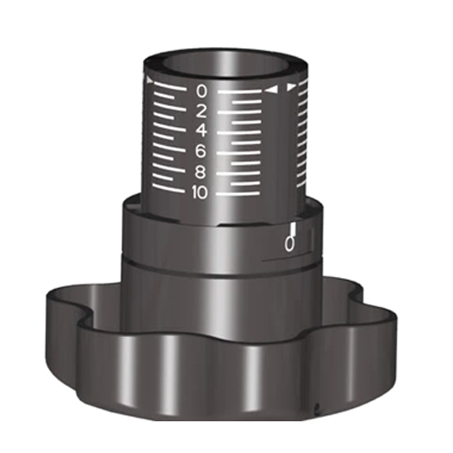
Hydraulic Balancing Valve Adjustment
DN20~DN500, there are four types of wheels, similar in structure and function, and all have two scales.
0~10 graduated horizontal line: represents 1 turn.
0~9 tens of numbers: represents 0.1 turn.
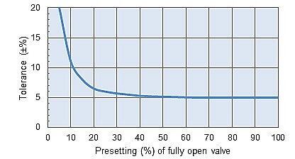
Tolerance Chart
Specification
| Class | 10K/150LB/PN10 | 16K/PN16 | PN25 |
| Working Pressure |
10 bar |
16 bar |
25 bar |
| Temperature |
-10~100 ℃ |
-10~100 ℃ |
-10~100 ℃ |
※The SB balancing valves have memory part, and the turns of hand wheel can be easily turned back to originally position
Kv Curves


Installation Position
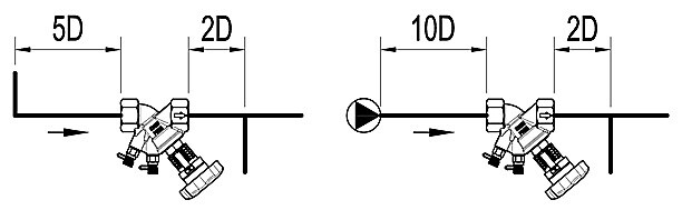
Recommendation:
The distance between the curved pipe and the branch pipe is at least over 5D and 2D.
The distance between the pump outlet and the branch pipe is at least over 10D and 2D.
※D is the caliber of the Balancing Valve