


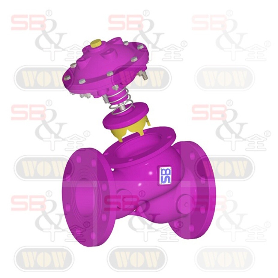
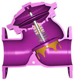
Water Control Valve-Basic Valve is controlled by the liquid pressure. It is a diaphragm control valve and mainly composed by two parts: Air-Chamber Set and Y-Shape Valve body. The Air-Chamber Set can be dismantled direct from the valve body during maintenance without dismantling the whole valve from the pipeline.
Y-Shape body design makes the valve have excellent hydromechanics. 25% Half-Direct Connection Design to reduce pressure loss. Besides, Fluid passes through the lower part of the valve cover, so the resistance of the fluid is less. Comparing with the same size of other control valves, Cv Value is larger.
41-00 Basic Valve is the foundation of all water control valves. It can join with different controllers to adapt different appliance situations, for example, Float Valve, Pressure Reducing Valve, Pressure Relief Valve, Pressure Sustaining Valve, Back Pressure Valve, Non-Slam Check Valve, Solenoid Control Valve, Rate of Flow Control Valve, Differential Pressure Relief Valve, etc. There are various kinds of valve sizes and connections for choice. The application situations are unlimited.

Comparison of valve

 |
 |
 |
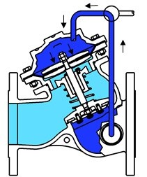
| ● Close ● |
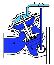
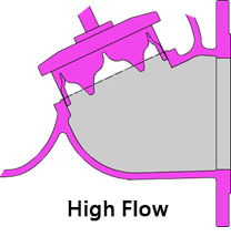
● Open ●
|
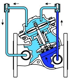
● Control ●
|
| When the pressure gets into the air chamber from the inlet of the valve, the valve will form an airtight seal. |
Once the fluid in the air chamber is discharged, there is no way to save the pressure in the air chamber. The valve will be opened and let the fluid pass through.
|
If the corresponding control appliance is assembled, the valve will automatically operate according to the pressure in the pipeline to guarantee the input/output pressure and rate of flow.
|
Connection Way
Working Temperature and Media
Operating Pressure
| Flange Class | Max. Working Pressure | |
| bar | psi | |
| 10K | 14 | 205 |
| 16K | 22 | 320 |
| 150LB | 17.4 | 250 |
| 300LB | 28 | 400 |
| PN16 | 16 | 235 |
| PN25 | 25 | 365 |
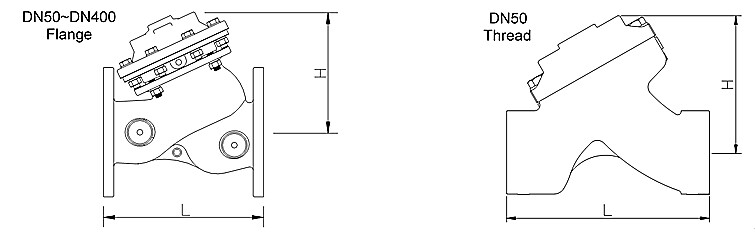
Dimension
|
Valve size
|
50 Tr
|
50 |
65
|
80
|
100
|
125
|
|
L (mm)
|
184 |
205
|
229 |
250
|
320
|
370
|
|
H (mm)
|
123 | 155 | 182 | 186 | 242 | 276 |
|
Weight (kg)
|
6 |
11
|
13 |
22
|
37
|
46
|
|
Valve size
|
150
|
200 |
250
|
300
|
350
|
400
|
|
L (mm)
|
415
|
500
|
605 |
725
|
733
|
990
|
|
H (mm)
|
308 | 418 | 488 | 572 | 598 | 866 |
|
Weight (kg)
|
75
|
125
|
217 |
370
|
380
|
846
|
Kv/Cv Value
|
Size
|
DN50 (2″)
|
DN60 (2.5″) |
DN80 (3″)
|
DN100 (4″)
|
DN125 (5″)
|
DN150 (6″)
|
|
Cv
|
66 |
100
|
140 |
240
|
460
|
590
|
|
Kv
|
57 | 86 | 120 | 205 | 395 | 510 |
|
Size
|
DN200 (8″)
|
DN250 (10″) |
DN300 (12″)
|
DN350 (14″)
|
DN400 (16″)
|
DN500 (20″)
|
|
Cv
|
990 | 1575 | 2290 | 3060 |
4000
|
5700
|
|
Kv
|
850 | 1355 | 1970 | 2630 | 3440 | 4900 |
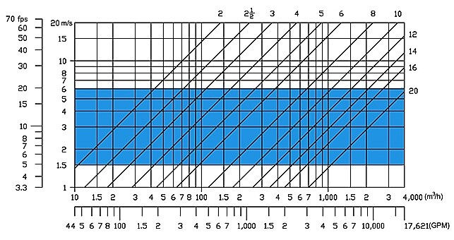
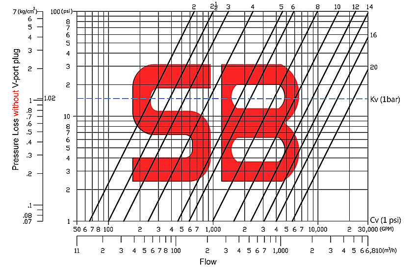
Valve Sizing Method
Pressure Loss Curve – Standard
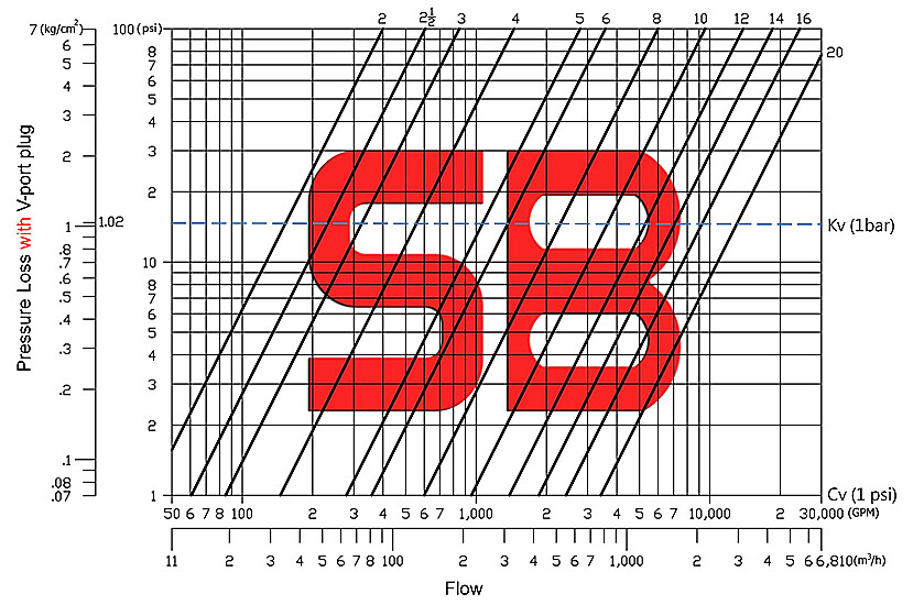
Pressure Loss Curve – V-port Plug
Cavitation Area
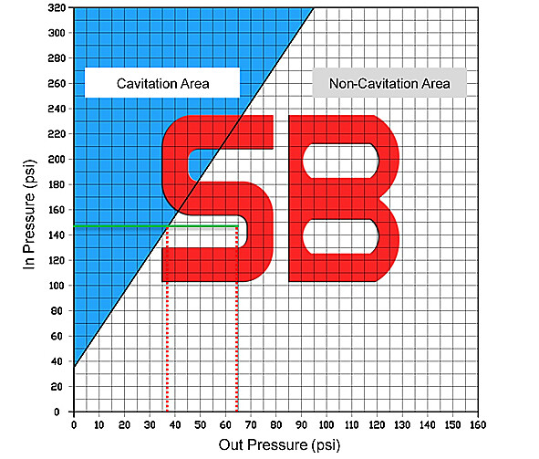
While acting as Pressure Reducing Valve or Pressure Relief Valve, cavitation may occur if pressure difference between valve’s inlet and outlet is greater enough. When water flow across valve seat and disk at high speed, water pressure will drop down. If pressure drops below the vapor pressure, vapor bubbles maybe formed. These bubbles will generate terrible damage to valve’s parts. And cavitation may cause vibration and noise.
A.Increase downstream pressure if possible. B.Select a larger valve in order to decrease flow velocity. C.Use more valves in parallel to reduce inlet pressure. D.For pressure reducing application, use more valves in serial to decrease the ΔP through a single valve.
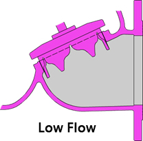
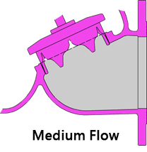
Option:V-port Plug
 |
V-port Plug A component installed at the bottom of the bonnet that interfere the flow between the bonnet and the valve body. Suitable occasions: low flow rate, high differential pressure. Changing the proportion of water volume that the spool opens to achieve the same volume of water, which has a longer opening stroke than a flat retainer. when the amount of water changes, the opening height of the valve can be adjusted automatically to stabilize the water flow and reduce noise and vibration. |
|
 |
 |
 |
Download